How rock conditions determine tunnel drilling equipment selection
auth.Prof. Heinrich AldenTime
Sep 25, 2026Click Count
A tunnel drive can appear straightforward during tender review: compare cutterhead diameter, installed power, thrust, and quoted advance capacity, then select the largest machine within budget. That approach breaks down when the face changes from blocky weathered rock to massive abrasive granite, or when a fault zone introduces water and fines into a drive planned for hard-rock excavation. The equipment may still be mechanically capable of boring, but cutter consumption, intervention frequency, energy draw, support delays, and schedule exposure can move far beyond the original assumptions.
The core decision is to select tunnel drilling equipment around the expected rock mass behavior, not around intact rock strength alone. Strength matters, but abrasivity, discontinuities, groundwater, stress conditions, and geological variability often determine whether a hard-rock TBM, shielded TBM, double-shield machine, roadheader, drill-and-blast spread, or hybrid approach will perform with acceptable risk. A useful selection process begins by translating ground investigation results into operating conditions the equipment must tolerate.
Start with the rock mass, not the laboratory strength value
Uniaxial compressive strength is often the first number seen in a geotechnical report. It is useful for estimating penetration resistance and cutter loading, yet it cannot independently define the excavation method. A strong but heavily fractured formation may break readily under a cutterhead, while a moderately strong, massive, quartz-rich formation can consume cutters rapidly and limit penetration. The machine encounters a rock mass with joints, bedding, fault infill, groundwater paths, and changing confinement—not a uniform test specimen.
Before comparing equipment proposals, separate the available geological information into five decision categories:
- Intact rock properties: compressive strength, tensile strength, hardness, mineral composition, and abrasivity.
- Rock mass structure: joint spacing, joint orientation, block size, bedding planes, foliation, faults, shear zones, and zones of weathering.
- Water conditions: seepage, inflow potential, groundwater pressure, permeability, and the likely presence of pressurized fractured zones.
- Stress and stability: overburden, in-situ stress, squeezing potential, rockburst potential, and convergence risk.
- Variability along the alignment: expected transitions, uncertainty between boreholes, mixed-face sections, and the length of each ground domain.
A selection review becomes more reliable when these categories are mapped by chainage rather than reduced to a project-wide average. A machine that is productive through most of a drive may still be the wrong choice if it cannot safely pass the ground section that controls schedule risk.
Hard, massive rock: penetration and cutter loading take priority
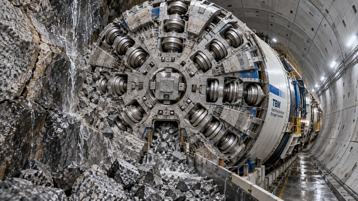
In competent, massive hard rock, the main question is whether the cutting system can generate sufficient penetration without overloading disc cutters, bearings, cutterhead structure, or the main drive. Hard-rock open TBMs can be effective where the ground stands unsupported and water is manageable. Their simpler arrangement can offer good access and efficient excavation in long, stable reaches. However, they depend on the rock mass remaining stable enough for the selected support sequence.
For this ground type, compare cutterhead design and cutter layout rather than looking only at installed power. The spacing, diameter, loading capacity, rotation behavior, and accessibility of disc cutters influence how efficiently the machine creates chips. Cutterhead openings must clear broken rock without allowing uncontrolled block movement. A cutterhead designed for a particular strength range may become inefficient when the formation is much harder, more brittle, or more abrasive than expected.
High strength can reduce penetration, but it does not automatically mean that the largest thrust system is best. Excessive thrust against a poorly matched cutter arrangement can accelerate wear, generate damaging vibration, and raise the likelihood of abnormal cutter failures. The evaluation should examine the manufacturer’s operating envelope for cutterhead torque, thrust, penetration per revolution, and allowable cutter loads under the anticipated rock conditions.
Abrasivity can control lifecycle cost
Abrasive minerals, particularly quartz-bearing rock, may have a larger commercial effect than strength alone. Abrasion attacks disc cutter rings, cutterhead wear protection, muck handling components, conveyors, transfer chutes, and slurry circuits where used. A relatively short abrasive section can require extensive spare-part planning if cutter changes are difficult or interventions require a pressurized environment.
Ask how abrasivity has been characterized and whether the test method represents the actual alignment. The review should connect abrasivity results to the proposed cutter material, gauge-cutter protection, scraper arrangement, wear detection, and stock of replacement components. Generic claims about “wear-resistant” cutters are not enough. The important issue is whether the design permits practical inspection and replacement at the expected frequency.

Fractured and blocky ground changes the machine requirement
A fractured rock mass may permit fast breakage, but it can create a different set of problems: overbreak, loose blocks at the crown, unstable face conditions, water pathways, and difficulties in maintaining a predictable excavation profile. In such conditions, selecting equipment only for high penetration can be misleading. Face control, support installation, and safe operation around changing ground become equally important.
Open hard-rock TBMs may remain suitable in competent fractured ground when block fall risk is limited and support can be installed promptly. Where the rock mass is more variable, a shielded arrangement can provide a protected working area and allow the machine to manage support installation behind or within the shield. A double-shield TBM can be attractive where long stable zones permit simultaneous boring and segment erection, while its gripper and shield functions offer more flexibility than a purely open machine. Its performance still depends on having enough competent ground for gripper reaction and enough clearance to avoid shield jamming in converging terrain.
Blocky ground also affects muck flow. Large fragments can obstruct cutterhead openings, damage belts, or create irregular loading on conveyors. The proposed machine should be reviewed for opening geometry, crusher capacity where included, discharge path, and the ability to handle oversized material without repeated manual intervention. A cutterhead that breaks rock efficiently but cannot transport the resulting fragments continuously will not deliver reliable advance.
Faults, weak zones, and mixed faces are often the selection boundary
Most alignment decisions are not controlled by the best ground. They are controlled by faulted, weathered, clay-filled, or mixed-face sections where hard rock occurs alongside weak material. These transitions can cause uneven cutterhead loading, loss of face support, increased convergence, and rapid changes in excavation behavior. They are particularly demanding when a tunnel is large enough that different materials occupy separate areas of the face.
Where weak or unstable material is expected, shielded excavation with segmental lining may provide more control than an open machine. The shield can support the surrounding ground while the lining ring is installed, reducing exposure between excavation and permanent support. Yet a shield is not a universal answer. In squeezing ground, convergence can create high friction around the shield, restrict movement, and increase the risk of machine entrapment. The design review must therefore consider shield diameter, articulation, overcut capability, tail clearance, lubrication provisions, and the response to predicted convergence.
Roadheaders and drill-and-blast methods can offer operational flexibility in shorter, highly variable, or geometrically complex sections. Roadheaders are generally most favorable in weaker to moderately strong rock where cutting picks can work efficiently and where selective excavation or frequent profile changes matter. In hard or abrasive rock, pick wear and low cutting rates may make them uneconomic. Drill-and-blast can accommodate abrupt geological change and non-circular shapes, but it introduces cyclic operations, vibration management, overbreak control, ventilation demands, and a more complex interaction between blasting, support, and mucking.
Groundwater is not a secondary equipment issue
Water can turn a manageable fractured formation into an operationally difficult one. Inflow may wash fines into the excavation, soften fault gouge, destabilize blocks, disrupt conveyor transfer points, and complicate support installation. Under pressure, it may require a closed-face system capable of maintaining controlled support at the face. The appropriate method depends on permeability, pressure, ground type, tunnel depth, and the consequences of settlement or loss of ground.
Technical reviewers should distinguish between isolated seepage and a credible pressurized inflow scenario. The first may be addressed through drainage, probe drilling, grouting, and robust dewatering arrangements. The second can affect the fundamental machine type. Where earth pressure balance or slurry operation is being considered, the ground’s ability to form and maintain a workable conditioning medium is central. Coarse, highly permeable, fractured ground may behave differently from fine-grained material, and the spoil treatment system must be sized for the actual mix of water, fines, and rock fragments.
Probe drilling capability, pre-excavation grouting provisions, pressure monitoring, emergency sealing arrangements, and access for intervention deserve attention during equipment selection. These features may not increase nominal boring speed, but they can determine whether the drive can cross an uncertain water-bearing zone without an extended stoppage.
Match the support method to the machine cycle
Excavation equipment cannot be evaluated separately from primary support and final lining. Rock bolts, mesh, shotcrete, steel sets, segmental lining, drainage measures, and invert construction each impose timing and space requirements. An open TBM may advance efficiently in sound ground, but its benefit is reduced if the support crew must stop boring frequently to stabilize fractured sections. A shielded TBM may provide a more controlled lining cycle, but its segment supply, ring build time, and tail-seal performance become production constraints.
The review should test the proposed cycle against adverse rather than ideal ground. Consider where bolts are installed, whether the machine provides safe access at the crown, how quickly shotcrete can be applied after excavation, and how support materials reach the face. For segmental systems, verify ring geometry, erector reach, storage capacity, gasket protection, annular-gap treatment, and the consequences of a delayed segment supply. The preferred machine is often the one whose support process remains workable when the ground deteriorates.
Use geological domains to compare equipment proposals
A practical way to avoid generic comparisons is to build a geological-domain matrix. Divide the route into zones with materially different rock behavior, then score each equipment option against the operating demands of each zone. The score should not be based solely on anticipated advance rate. It should capture the probability and consequence of reduced penetration, cutter replacement, support delay, face instability, water inflow, shield jamming, and difficult recovery.
For every major domain, request a defined operating response. In competent abrasive rock, the response may include a cutter replacement strategy and wear-part inventory. In fractured ground, it may specify probe drilling, reduced advance increments, additional support positions, or modified cutterhead opening management. In a fault zone, it may require pre-grouting, altered face pressure, conditioning changes, or a planned shift to a different excavation method. Proposals that describe only normal operation leave the most important selection questions unanswered.
Questions that expose weak assumptions
- Which ground parameters were used to select cutter type, cutter spacing, and cutterhead opening ratio?
- What is the expected operating response when jointed rock produces blocks larger than the normal muck flow can accept?
- How will the machine maintain progress through a mixed face rather than a uniform formation?
- What conditions would require changes to thrust, torque, penetration, cutter inspection frequency, or support sequence?
- How are water inflow and fines expected to affect the muck removal system?
- What recovery provisions are included if convergence, unstable ground, or unexpected abrasion prevents normal advance?
Do not treat geological uncertainty as a footnote
Boreholes and mapping reduce uncertainty, but they cannot reveal every localized fault, cavity, stress change, or water path. Equipment selection should therefore include a realistic uncertainty allowance. This does not mean selecting the most complex machine by default. It means identifying which unknowns could invalidate the chosen method and ensuring that the equipment, support plan, and contract approach have credible responses.
Where uncertainty is concentrated in a few critical sections, a staged strategy may be more defensible than forcing one machine concept across the entire alignment. This can include additional investigation ahead of the face, planned transition zones, alternative support materials, spare cutting tools, and predefined decision triggers. The trigger should be observable: rising cutter wear, increasing torque at unchanged penetration, persistent shield friction, growing water inflow, excessive overbreak, or changes in convergence. Linking these field signals to actions helps prevent a geological surprise from becoming a prolonged equipment problem.
The strongest selection decision is not the machine with the highest advertised production figure. It is the equipment arrangement whose cutter system, face-control capability, muck handling, support cycle, and recovery options remain aligned with the hardest credible rock conditions along the route.
Recommended News
- 00
0000-00
How rock conditions determine tunnel drilling equipment selectionTunnel drilling equipment selection starts with rock conditions. Explore how strength, abrasivity, fractures, groundwater, and support needs shape safer, more productive tunnel drives. - 00
0000-00
How a tunnel boring guidance system controls alignment errorTunnel boring guidance system insights: learn how laser, inertial, and survey data control alignment error, reduce risk, and support precise TBM steering. - 00
0000-00
Does reducing rock breaker noise require retrofitting or can it be addressed at the operational level?Reduce rock breaker noise effectively—no retrofitting required. Discover proven operational tactics operators use daily to cut decibels, boost compliance, and protect hearing—starting now.
000000-00
{item.title}{item.description}Search News
Industry Portal
Hot Articles
- When industrial material handling solutions reduce dust exposureIndustrial material handling solutions reduce dust exposure through enclosed transfers, controlled flow, targeted extraction, and maintainable designs that protect workers and uptime.
- How rock conditions determine tunnel drilling equipment selectionTunnel drilling equipment selection starts with rock conditions. Explore how strength, abrasivity, fractures, groundwater, and support needs shape safer, more productive tunnel drives.
- What a compliance review checklist should cover before a mining safety auditCompliance review checklist for mining safety audits: verify equipment, training, risk controls, maintenance, and emergency readiness before inspectors arrive.
Popular Tags