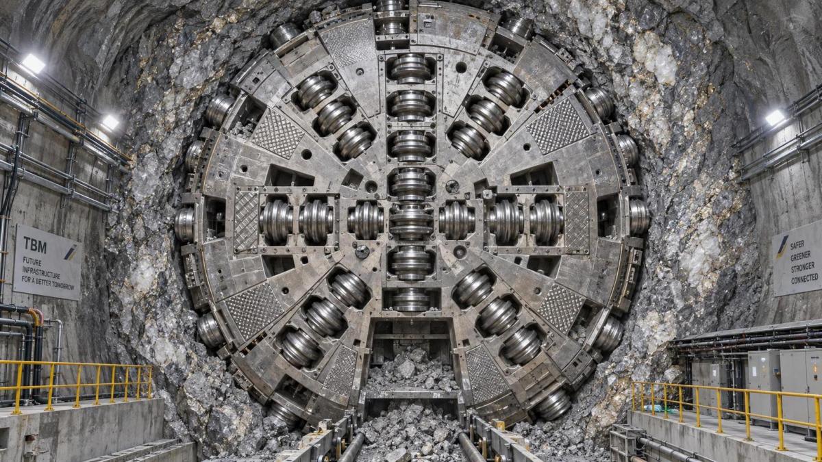
How TBM cutterheads should match abrasive rock conditions
auth.Prof. Heinrich AldenTime
Sep 12, 2026Click Count
Abrasive rock does not justify a single “heavy-duty” cutterhead specification. The correct match depends on how abrasivity interacts with rock strength, brittleness, jointing, groundwater, and the TBM’s thrust and torque envelope. A cutterhead that survives high-quartz granite may be inefficient in blocky abrasive sandstone; a design optimized for penetration in massive hard rock can suffer excessive gauge wear, poor muck discharge, or damaging vibration when the face becomes heterogeneous.
The decisive question is not whether the formation is abrasive, but what is being worn, at what rate, and under what cutting mechanism. Disc cutter rings, carbide inserts, cutter housings, buckets, wear plates, grizzly bars, peripheral structures, and the cutterhead body do not face the same damage mode. Effective TBM cutterhead selection begins by separating these mechanisms rather than treating cutter consumption as one generic wear problem.
Start with the rock mass, not the cutter catalogue
Uniaxial compressive strength (UCS) is necessary but insufficient. It indicates the force needed to fracture intact rock, but it does not reliably predict cutterhead wear. A moderately strong rock with high quartz content and angular grains can be more damaging to exposed steel components than a stronger, less abrasive lithology. Conversely, very strong but competent rock can primarily challenge cutter load capacity, bearing life, and available thrust rather than external wear protection.
A credible cutterhead assessment should combine intact-rock properties with rock-mass conditions:
- Strength and brittleness: UCS, tensile strength, and fracture behavior influence required cutter force, cutter spacing, penetration per revolution, and torque demand.
- Abrasivity: Cerchar Abrasivity Index (CAI), petrographic mineral composition, quartz content, grain size, and grain angularity help identify likely metal-loss mechanisms. No single abrasivity value should be used as a complete design basis.
- Jointing and discontinuities: Joint spacing, orientation, infill, fault zones, and rock quality affect fragmentation, impact loading, cutter chipping risk, and the likelihood of overbreak or block falls.
- Groundwater: Water pressure, flow paths, and fines transport can accelerate wear, complicate cutter changes, and alter the efficiency of muck removal.
- Geological variability along the alignment: The design case should include transitions, not merely the longest homogeneous reach. Mixed lithology frequently dictates the practical operating range.
Laboratory abrasivity testing is valuable when interpreted alongside petrography and core logging. CAI can support comparative assessment of formation sections, but it does not independently establish cutter-ring life or cutterhead-body wear. Test results can be affected by sample condition and local mineral distribution. Thin abrasive bands, altered zones, and hard mineral veins may have an outsized operational effect even if they are underrepresented in core samples.
Technical evaluations should therefore turn the ground investigation into a chainage-based ground model. Each section should identify expected rock strength, abrasivity, blockiness, water condition, and geological uncertainty. The cutterhead is then assessed against the most demanding credible combinations, including transition zones where wear and instability may occur together.

Cutterhead architecture must reflect the excavation mode
In hard, abrasive rock, the cutterhead’s primary task is to transfer thrust through the disc cutters efficiently while maintaining enough structural stiffness to preserve cutter geometry under load. That requirement creates a recurring trade-off: a more open face improves muck flow and can reduce re-crushing, while a more closed and heavily reinforced structure may better resist bending, local wear, and impact.
For competent, massive hard rock, cutterhead opening ratio is often selected to support chip evacuation without sacrificing the rigidity needed to keep cutter mounts stable. Poor discharge causes fragmented rock to circulate at the face. This re-crushing increases torque demand and exposes buckets, spokes, and wear plates to abrasive sliding. A face that appears sufficiently open on a drawing may still perform poorly if the openings, bucket geometry, and material flow path do not suit the expected fragment size distribution.
Where the rock mass is heavily fractured or contains frequent weak seams, the concern shifts. Larger blocks may enter openings irregularly, fines may accumulate in corners, and impact loading can become more severe. In such conditions, cutterhead openings and bucket transitions require protection against both abrasive flow and block impact. The cutterhead must also avoid geometries that trap material and create asymmetric loading.
The selected TBM type changes the design constraints. An open or gripper TBM operating in stable hard rock can use a cutterhead arrangement focused on rock-breaking efficiency and free muck removal. Shielded hard-rock TBMs may face tighter constraints around cutter access, excavation chamber geometry, and shield interaction. In water-bearing or unstable abrasive ground, the cutterhead cannot be evaluated separately from the machine’s ground-support concept, face pressure requirements, muck transport system, and intervention method.
A common mistake is to specify maximum structural mass as a substitute for design suitability. Extra steel can improve local durability, but it also increases rotational inertia, affects torque response, and may reduce useful opening area. The better criterion is whether the structure has adequate stiffness, fatigue resistance, wear allowance, and load paths for the anticipated cutter forces and operational transients.
Disc cutter layout is a wear-management decision
Disc cutters break rock by inducing compressive stress and fractures beneath the cutter ring. Their arrangement determines how effectively adjacent cuts interact. In abrasive ground, layout affects not only penetration rate but also the number of cutter changes, the distribution of wear across the face, and the risk that one worn cutter creates secondary damage elsewhere.
Cutter spacing should be matched to rock strength, expected penetration, and cutter diameter. Spacing that is too wide can leave ridges between cutter paths, raising forces and encouraging uneven loading. Spacing that is too tight can increase redundant crushing and torque without delivering proportional advance. The appropriate relationship is not fixed; it depends on the rock’s ability to form chips and on the intended operating penetration.
Center cutters, face cutters, transition cutters, and gauge cutters operate under different conditions. Gauge cutters are especially important in abrasive formations because they maintain tunnel profile while operating at high rolling speed and near the cutterhead periphery. They may experience severe ring wear, side wear, and elevated exposure to abrasive material flow. Underestimating gauge protection can lead to loss of excavation diameter, increased steering difficulty, and premature replacement of surrounding components.
Larger diameter disc cutters can offer higher load capacity and may reduce the cutter count required for a given face design. They are not automatically the best answer for every abrasive rock project. The selected cutter must remain compatible with the available thrust, torque, cutterhead geometry, access space, and planned maintenance method. A larger cutter subjected to insufficient normal force will not achieve its intended cutting performance; a high-capacity cutter operating in a highly fractured formation may encounter shock conditions that require particular attention to bearing and seal robustness.
Cutter-ring material and heat treatment require the same application-specific discipline. Ring hardness, toughness, carbide insert configuration, and resistance to thermal or impact damage must be considered as a system. A ring optimized only for abrasion resistance can become vulnerable to chipping or cracking if the formation includes hard inclusions, abrupt lithological transitions, or repeated impact from blocks. The technical objective is controlled wear, not maximum hardness in isolation.
Protect the cutterhead body where abrasive flow is concentrated
Disc cutters are consumable components by design. The more expensive risk is uncontrolled wear of the cutterhead structure or components that cannot be replaced without major intervention. Abrasive material does not wear every surface uniformly. It concentrates at the outer circumference, leading edges of buckets and spokes, cutter housings, discharge openings, and zones where material changes direction or recirculates.
Wear protection should therefore be zoned rather than uniformly applied. Replaceable wear plates, hardfacing, carbide-enhanced protection, sacrificial blocks, and reinforced bucket lips each have a role, but the correct choice depends on access, expected wear pattern, weldability, and the consequence of failure. A hardfaced surface may resist sliding abrasion effectively but can be unsuitable where repeated impact or cracking of the base material is the dominant threat. Replaceable protection is attractive only if it can be accessed and changed within the project’s intervention constraints.
Hardfacing deserves close scrutiny during technical evaluation. Deposit chemistry, dilution into the base metal, thickness control, cracking behavior, and repair procedure all affect performance. Excessively hard overlays may crack under impact or may be difficult to restore in confined conditions. The design documentation should identify protected zones, nominal wear allowance, attachment method, inspection criteria, and the limit at which renewal is required.
Particular attention is needed around cutter housings. Even when a cutter can be changed quickly, wear or deformation of the housing can compromise alignment and load transfer. This can accelerate ring wear, damage seals, and create a cycle in which a nominally consumable issue becomes a structural repair. Housing design should be reviewed for replaceable wear interfaces, weld access, drainage, and protection from direct abrasive flow.
Water and fines change the reliability picture
In dry abrasive rock, wear is often dominated by mineral contact and re-crushing. Water-bearing conditions introduce additional concerns: transport of abrasive fines into gaps, corrosion exposure, erosion at high-velocity flow paths, reduced visibility during intervention, and potential difficulty maintaining stable face conditions. Water does not necessarily reduce abrasive wear; slurry-like mixtures can carry sharp particles into areas that would otherwise see limited contact.
Cutter sealing and bearing protection are therefore central to cutter selection. A disc cutter may retain a serviceable ring profile yet fail prematurely if abrasive fines or water compromise the sealing system. Technical comparisons should not stop at cutter diameter and rated load. They should examine sealing arrangement, bearing capacity, lubrication concept, pressure equalization where applicable, cutter-change method, and inspection provisions.
Groundwater also affects maintainability. The expected cutter-change interval must be considered together with the time and conditions required to perform the change. A design that achieves good nominal cutter life but requires difficult access to high-wear positions can still produce unacceptable downtime. The practical measure is not merely cutters consumed per metre; it is the combined effect of cutter consumption, intervention duration, safety controls, and lost production.
Machine operating limits must support the selected design
A cutterhead cannot compensate for a mismatch between geological demand and TBM capability. The selected configuration must be checked against available thrust, torque, rotational speed, installed power, gripper or shield reaction capacity, and conveyor or muck-handling performance. In abrasive hard rock, attempts to preserve cutter life by reducing penetration can be counterproductive if they increase the number of revolutions required per metre. More revolutions can mean more sliding abrasion, more wear on peripheral components, and higher cumulative bearing exposure.
The operating window should be defined around penetration per revolution, cutter load, cutterhead rpm, torque margin, and allowable vibration. These parameters must be evaluated together. High penetration at inadequate cutter load distribution may overload selected positions; high rpm in abrasive conditions can increase wear rate; insufficient torque reserve can cause unstable operation during hard bands or poor muck discharge.
Monitoring capability matters because geology rarely conforms perfectly to the baseline model. Cutterhead torque, thrust, penetration, rpm, vibration, cutter temperature where available, and muck characteristics can reveal changing cutting conditions. The value of these signals depends on having a predefined response logic: when trends indicate abnormal wear, the team needs criteria for inspection, parameter adjustment, or cutter replacement rather than relying on production loss to reveal the problem.
Evaluate maintainability as part of cutterhead selection
In abrasive rock, cutterhead lifecycle performance is strongly influenced by how predictable and manageable maintenance is. Cutter-change access should be reviewed position by position, especially for center and gauge cutters. The evaluation should cover lifting arrangements, fastening accessibility, required tooling, cutter retention design, debris tolerance, inspection access, and the ability to remove damaged components without creating secondary repairs.
Wear-part interchangeability can reduce logistical complexity, but complete standardization is not always optimal. Gauge cutters and highly loaded face positions may require different specifications. What matters is that the bill of materials reflects the expected wear map and that critical spare components are defined for the project’s likely intervention scenarios.
Supplier documentation should make it possible to inspect the logic behind the design. Useful evidence includes cutter layout drawings, load calculations, structural analysis assumptions, wear-protection maps, material specifications, welding and repair procedures, cutter-change procedures, and limits for allowable wear. Claims of abrasion resistance without clear material, geometry, and renewal details do not provide a sufficient technical basis for selection.
The strongest specification is scenario-based
Abrasive rock conditions should be converted into operating scenarios rather than reduced to a single maximum UCS or CAI figure. One scenario may represent massive high-strength quartz-rich rock at target penetration; another may represent fractured abrasive rock with block impact; a third may address water-bearing transition zones with fines migration. The cutterhead should demonstrate acceptable cutter loading, structural margin, muck flow, wear protection, and maintainability across those conditions.
The preferred TBM cutterhead is not necessarily the one with the highest nominal cutter capacity, the greatest amount of hardfacing, or the largest number of cutters. It is the design that preserves cutting geometry, controls wear in accessible components, avoids damaging recirculation of abrasive muck, and remains compatible with the machine’s real operating envelope. In abrasive tunnelling, reliability comes from matching the full excavation system to the rock mass—not from treating the cutterhead as an isolated wear part.
Recommended News
- 00
0000-00
How TBM cutterheads should match abrasive rock conditionsTBM Cutterheads for abrasive rock: learn how geology, cutter layout, wear protection, muck flow, and maintenance strategy improve tunnelling reliability. - 00
0000-00
How rock mechanics testing helps predict excavation risksRock mechanics testing helps predict excavation risks by assessing strength, fractures, groundwater, and deformation for safer, smarter project decisions. - 00
0000-00
When should a mining project hire geomechanics consultants?Geomechanics consultants help mining projects manage slope, ground support, water, and infrastructure risks early—discover the key hiring triggers.
000000-00
{item.title}{item.description}Search News
Industry Portal
Hot Articles
- What to check before choosing an aggregate production line manufacturerChoose an aggregate production line manufacturer with confidence. Explore key checks for capacity, product quality, layout, service, lifecycle cost, and reliable project delivery.
- When does open-pit mining fleet electrification cut haulage costs?Mining Fleet Electrification open pit: learn when electrified haulage lowers cost per tonne through reliable power, stable routes, high utilization and smarter charging.
- How TBM cutterheads should match abrasive rock conditionsTBM Cutterheads for abrasive rock: learn how geology, cutter layout, wear protection, muck flow, and maintenance strategy improve tunnelling reliability.
Popular Tags